Orchard Sprayers
Air Delivery Sprayers
Air delivery or air blast sprayers are used to apply pesticides, plant growth regulators and foliar nutrients to orchard trees. They apply these materials as liquids carried in large volumes of air. Air blast sprayers have adjustments in the fluid and air delivery systems that permit tailoring applications to fit a wide range of orchard conditions.
The efficiency and cost effectiveness of orchard pest management programs are influenced by the skills of managers and sprayer operators who evaluate orchard conditions and alter machine settings and operating techniques to optimize performance of sprayers. A combination of operational skill, equipment performance, timing and chemical selection is necessary for optimal results.
Selecting a Sprayer
A sprayer must be adequate for the worst of orchard conditions; one that is adequate only under favorable conditions is a liability under adverse conditions. Sprayers should at least meet the demands of spraying large, thick trees under the poorest conditions allowable for spraying. Consider reliability, maintenance history and the ability to cover the projected acreage in selecting spray equipment.
Horsepower requirement is a very important consideration because fans must move a considerable weight of air and materials. Manufacturers provide recommended horsepower range, but reliability and equipment longevity are often enhanced by selecting from the upper range of suggested horsepower.
A good practice is to observe sprayers operating in orchards where tree size, row spacing, weather, speed, application volume, and so on, are challenging and examine the coverage. Request dealer demonstrations and ask for names and locations of customers who are operating models of interest. Consult university personnel, pesticide industry representatives, and growers or custom applicators that operate sprayers. When observing a demonstration, try to relate demonstration conditions and operating techniques such as speed, pressure, nozzle output volume, etc., to the more challenging conditions you anticipate.
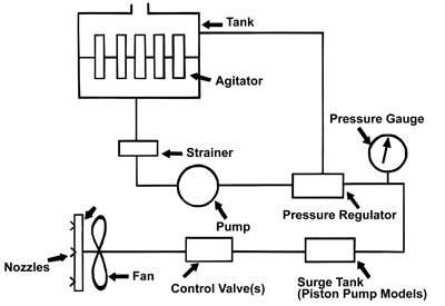 Figure 1. Basic components of an air blast sprayer.
All sprayers have components that are necessary for good operation. The following are a few suggestions for these components.
Tanks for sprayers should be corrosion-resistant and designed for ease in filling and adding pesticides, and for rapid, complete drainage to facilitate cleaning. Agitation should be sufficient to keep all materials uniformly distributed throughout the tank. Wettable powder pesticide formulations require vigorous agitation. Paddle or propeller type mechanical agitators and hydraulic jet agitators are common. Regardless of design, thorough agitation is required, both when trees are being sprayed and when spray nozzles are shut off. Pesticides settling in tank mixtures may cause spray equipment problems and reduce pesticide effectiveness.
Pumps for orchard sprayers are usually piston or centrifugal units. Centrifugal pumps move a high volume of liquid at low to medium pressure. Piston pumps are usually selected for high pressure applications.
Pressure Regulators are variable orifice devices that are opened or closed to change system pressure. With air blast sprayers, pressure regulators are primarily used to divert varying amounts of the pump output back to the tank. They are often referred to as pressure relief valves or unloading valves. Actual spray output is seldom governed by pressure regulators on air blast sprayers. Spray pressure is sometimes regulated by varying pump speed, and it can also be regulated by varying engine RPM. Accordingly, it is very important to maintain consistent engine speed so the RPMs of the sprayer PTO remain in the range needed.
Pressure Gauges are monitors of spray system operation. Experienced operators will quickly observe spray system malfunctions that visibly reduce spray output and pattern. Malfunctions that cause 10 to 20 percent changes in spray output, however, may easily go unnoticed. Pres-sure gauges indicate spray manifold pressure. Because a sprayer is set up to operate within a specified pressure range, the pressure gauge should alert the operator when a malfunction has changed manifold pressure. Malfunctions can arise from restricted or clogged strainers (particularly line strainers), restricted or leaking lines, changes in pump output, pressure regulator malfunctions, and so on.
Control Valves may simply be off/on valves but, most often, they provide manifold selection options. Valves may be manually operated or operated by electric solenoids. Mount valve controls within easy reach of the operator.
Manifolds deliver spray to nozzles and typically allow selective nozzle placement to achieve the desired spray pattern.
Spray Nozzles meter spray liquid and atomize the spray (influencing droplet size and the number of droplets obtained from a given volume of liquid). Nozzle type and location also influence spray pattern. Nozzles usually have several components including a body, cap, strainer, disc and core (orifice and whirl plate). The disc and core, or tip, are quite susceptible to wear. Wear resistant and chemical corrosion resistant materials such as hardened stainless steel, tungsten carbide or ceramic material, are usually selected. Even so, check nozzle output periodically and make adjustments for nozzle wear, as even a small amount of wear can significantly increase flow. For example, the flow rate of a D6 disc is increased 36 percent with only 0.005 of an inch of wear.
Fans, both axial and centrifugal, are used on air blast sprayers. The airstream’s major function is moving spray into trees and enhancing the uniformity of pesticide deposit on fruit, foliage and wood. Air movement also displaces leaves and branches, which aids spray penetration and increases the exposure of surfaces to spray. The air stream assures spray droplet velocity, which increases impingement (sticking) of very small spray droplets to the target. The air stream conveys the spray into the tree canopy and helps atomize the spray. Some systems depend on the air stream for atomization, although most sprayers depend primarily on nozzles. The effect of the air stream on spray droplet size is proportional to the relative velocity difference between the liquid spray and the air stream. The greater the velocity difference, the greater the atomization. If the nozzle injects spray into the air stream moving in the same direction as the air, the spray droplet break-up caused by the air forces will be minimal. Injecting spray directly into (against) the air stream produces the maximum degree of atomization.
Air stream characteristics that influence coverage include air volume (CFM: cubic feet per minute) and velocity (FPM: feet per minute). These parameters are influenced by fan type and speed, size, volute design, and so on. As these and previous comments indicate, a number of factors, most being interactive rather than independent, are involved in air delivery sprayer performance. Performance data concerning many of these factors for specific sprayers are not generally available.
Sprayer Setup
Setup of an air blast sprayer includes selection and placement of nozzles, orienting air director vanes and other air control devices, and setting pressure, throttle and engine speed.
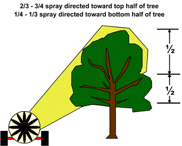 Figure 2. Recommended proportioning of spray volume.
Nozzle arrangement and air guide or director vane settings should place most of the spray in the top half of trees, where most of the foliage and fruit are located. Air blast sprayers are typically set up to apply ⅔ to ¾ of the spray to the top half of trees, and ⅓ to ¼ to the bottom half (Figure 2). This targeted spraying is accomplished by placing more or larger nozzles on manifolds in the area that supplies spray to the upper half of trees and setting the air directors on the fan outlet to direct the air stream accordingly. Consider tree growth and target pest habits in determining the setup for specific applications.
Nozzle selection decisions influence the gallons of spray per acre that will be applied and sprayer speed. Orchard spray volumes vary from 30 to 150 gallons per acre (GPA). Table 1 contains a recommended application rate based on tree size. Sprayer speeds range from one to three miles per hour, most commonly 1.5 to 2.0 miles per hour (MPH). Better coverage is obtained at the lower speeds and at wind speeds below 5 miles per hour.
| Table 1. Recommended total spray volume of application for pecan. | |
| Tree Height (feet) |
Total Volume (gallons per Acre) |
| Up to 25 | 25 |
| 25 to 50 | 50 to 90 |
| 50 and up | 100 to 150 |
Other items that must be determined are spray system pressure (PSI), the number of nozzles on the sprayer, and the tree row spacing. Manufacturers usually recommend operation within a specified pressure range, normally 60 to 260 PSI for sprayers with conventional hydraulic nozzles. Many manufacturers also provide nozzle setup suggestions.
Sprayer setup decisions are made using information from pesticide labels, operator manuals, extension recommendations, anticipated orchard conditions, and experience. Factors can be listed as known and unknown.
Known will include:
- GPA (gallons per acre) desired
- PSI (pounds per square inch) pressure desired
- MPH (miles per hour) desired
- Number of nozzles on sprayer
- Tree row spacing
- Spraying one or both sides of the sprayer
The information that needs to be determined and set for the machine can be listed as unknowns:
- GPM (gallons per minute) output needed
- Nozzles (sizes and placement)
Gallons per minute output for a sprayer traveling between each row and spraying from both sides can be calculated with the following equation:
GPM = (GPA x MPH x Row Spacing(ft)) ÷ 495(spraying both sides)
Gallons per minute output for a sprayer traveling between each row and spraying from one side only and both sides of the tree can be calculated with the following equation:
GPM = (GPA x MPH x Row Spacing(ft)) ÷ 990(spraying one side)
Nozzle sizes can be selected from the manufacturer’s catalogues using the calculated GPM, the selected pressure (PSI), and number of nozzle positions on the sprayer. Arrange nozzles so that ⅔ to ¾ of the spray will be applied to the top half of trees, with the residual applied to the bottom half. Calculating the average nozzle output will help in making nozzle selections from the manufacturer’s tables.
Example:
Known:
- GPA = 100
- PSI = 150 at the manifold
- MPH = 1.5 (selected travel speed)
- Number of nozzles = 16
- Tree row spacing = 60 feet
- Spraying out one side of sprayer on both sides of tree
Unknown
- Gallons per minute output needed
GPM = (GPA x MPH x Row Spacing(ft)) ÷ 990(spraying one side)
GPM = 100 x 1.5 x 60 ÷ 990(spraying one side) = 9
- Nozzles (sizes and placement).
There are 16 on each side. Select 16 nozzles that have a combined output of 9 GPM/side. Arrange nozzles to provide the desired volume in the top half of trees for one side, and then select nozzles for bottom half.
Determine the average nozzle output as a starting point for making nozzle selections from the manufacturer’s tables. This can be calculated as follows:
9 GPM ÷ 16 Nozzles = 0.56 GPM Nozzle
To place ¾ of the spray volume in the top half of trees, the nozzles placed on the top half of each manifold will need a combined output between ¾ x 9 GPM = 6.75 GPM.
Use the manufacturer’s table to find 16 nozzles having a combined capacity of approximately 9 GPM that can be mounted on the sprayer manifold, with between 6 and 6.75 GPM applied to the top half of trees.
Most spray nozzle manufacturers publish tables showing the GPM capacity of various nozzle sizes for various pressures. Table 2 is part of a manufacturer’s nozzle capacity table.
| Table 2. Nozzle Capacity Data (Spraying Systems, Inc.) | |||||
| Disc and Core Nozzles | Liquid Pressure in P.S.I. |
Capacity in G.P.M. per Nozzle |
Disc and Core Nozzles | Liquid Pressure in P.S.I. |
Capacity in G.P.M. per Nozzle |
| D3-23 | 40 | 0.12 | D4-45 | 40 | 0.36 |
| 60 | 0.14 | 60 | 0.43 | ||
| 80 | 0.16 | 80 | 0.50 | ||
| 100 | 0.18 | 100 | 0.56 | ||
| 150 | 0.21 | 150 | 0.68 | ||
| 250 | 0.26 | 250 | 0.86 | ||
| 400 | 0.32 | 400 | 1.11 | ||
| D3-25 | 40 | 0.19 | D5-45 | 40 | 0.45 |
| 60 | 0.23 | 60 | 0.55 | ||
| 80 | 0.26 | 80 | 0.64 | ||
| 100 | 0.29 | 100 | 0.71 | ||
| 150 | 0.35 | 150 | 0.86 | ||
| 250 | 0.44 | 250 | 1.11 | ||
| 400 | 0.55 | 400 | 1.40 | ||
| D3-45 | 40 | 0.23 | D7-25 | 40 | 0.53 |
| 60 | 0.28 | 60 | 0.63 | ||
| 80 | 0.33 | 80 | 0.73 | ||
| 100 | 0.36 | 100 | 0.81 | ||
| 150 | 0.44 | 150 | 0.98 | ||
| 250 | 0.56 | 250 | 1.27 | ||
| 400 | 0.71 | 400 | 1.59 | ||
| D4-25 | 40 | 0.29 | D7-45 | 40 | 0.68 |
| 60 | 0.35 | 60 | 0.84 | ||
| 80 | 0.40 | 80 | 0.97 | ||
| 100 | 0.45 | 100 | 1.11 | ||
| 150 | 0.54 | 150 | 1.35 | ||
| 250 | 0.68 | 250 | 1.75 | ||
| 400 | 0.86 | 400 | 2.25 | ||
Two or more nozzle sizes are normally required to produce the desired spray volume and pattern. A variety of nozzle arrangements can be used to achieve the volume and spray distribution needed. A good selection would be as follows (Figure 3).
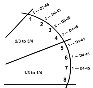 Figure 3. Nozzle placement for proportioning spray material on each manifold.
| Top Tree Half | |||
| Tip Size | Number Nozzles on Boom |
Capacity (GPM) |
Total (GPM) |
| D7-45 | 1 | 1.35 | 1.35 |
| D6-45 | 2 | 1.15 | 2.30 |
| D5-45 | 2 | 0.86 | 1.72 |
| D4-45 | 2 | 0.68 | 1.36 |
| Top Half Total | 6.73 | ||
6.73 GPM/side or 75 percent
| Bottom Tree Half | |||
| Tip Size | Number Nozzles on Boom |
Capacity (GPM) |
Total (GPM) |
| D5-45 | 1 | 0.86 | 0.86 |
| D4-45 | 2 | 0.68 | 1.36 |
| Bottom Half Total | 2.22 | ||
2.22 GPM or 25 percent
Air Blast Sprayer Calibration
Calibration is the process of measuring and adjusting the gallons per acre of spray actually applied. Sprayers need to be calibrated to meet the coverage needs of the orchards to be sprayed and to facilitate precise dosing of each material. A sprayer should be set up to apply a gallon per acre rate at a desired speed and pressure. In-orchard calibration frequently indicates a need for adjustments to achieve the target gallons per acre.
Speed of travel of a sprayer is a vital factor in obtaining the number of gallons of spray per acre desired. Change in gallons per acre (GPA) applied is inversely proportional to the change in speed. If speed is doubled, the gallons per acre will be halved, so if nozzles have been installed and pressure set to provide a gallon per acre rate at a certain speed, the sprayer should apply the GPA rate at that speed.
To determine the travel speed, measure a known distance. Use fence posts or flags to identify this distance. A distance more than 200 feet and a tank at least half full are recommended. Travel the distance determined at your normal spraying speed and record the elapsed time in seconds. Repeat this step and take the average of the two measurements. Use the following equation to determine the travel speed in miles per hour:
Travel Speed(MPH) = (Distance(feet) x 0.68) ÷ Time(seconds)
(0.68 is a constant to convert feet/second to miles/hour)
Check Gallons per Minute Output
The gallons per minute output required for a sprayer traveling along both sides of each row spraying from one side for a desired gallon per acre rate can be calculated with the following equation:
GPM(req) = (GPA x MPH x Row Spacing(ft)) ÷ 990(spraying one side)
(If one pass is made between rows spraying from both sides of the sprayer, use 495 as constant.)
GPA = Gallons Per Acre
MPH = Miles Per Hour
To check actual output:
- Fill sprayer with water. Note the level of fill. If a material with considerably different flow characteristics than water is to be sprayed, fill the sprayer with this material.
- Operate the sprayer at the pressure that will be used during application for a measured length of time. A time period of several minutes will increase accuracy over a time period of 1 minute.
- Measure the gallons of liquid required to refill sprayer to the same level it was prior to the timed spray trial with the sprayer in the same position as when it was filled initially. The actual GPM can be calculated as follows:
GPM(actual) = Gallons to refill sprayer ÷ Minutes of spray time - Calculate the GPA being applied by the sprayer.
GPA = (GPM(actual) x 990 (spraying from one side)} ÷ MPH x Row Spacing(ft)
If the actual GPA is slightly different from the required GPA, the actual GPA can be increased or decreased by increasing or decreasing spray pressure on sprayer models that have provisions for adjusting pressure. Only small output changes should be made by adjusting pressure. Make major changes in output by changing nozzles.
References
Cromwell, R. R. 1975. Citrus growers’ guide to air spraying. Florida Cooperative Extension Service Circular 351. p. 31.
Weed Control Sprayers
Orchard herbicide sprayers must be able to efficiently place herbicides on the orchard floor with minimal risk to the trees. Successful orchard herbicide application requires: (1) appropriate herbicide selection, (2) proper timing of applications, and (3) correctly adjusted, calibrated and operated spray equipment. Boom sprayers are the predominant orchard herbicide sprayers. They operate at low spray pressure and volume. Sprayers can be mounted on or pulled behind a tractor. Figure 4 depicts a well-conceived sprayer design.
Components
Tanks of corrosion-resistant metals and plastic-lined and fiberglass tanks are available in a variety of sizes. Sprayer tanks should have a large filling hole to facilitate easy filling, inspection and cleaning of the tank. A strainer to filter out debris, which is easily introduced during loading, is also needed. Tanks should also have drains for fast, complete drainage without exposing workers to herbicide.
Provide strainers in the locations shown in Figure 4. In-line strainers can be provided as optional equipment. Strainers are especially important where wettable powders are used. In-line and nozzle strainers are generally 50- to 100-mesh screens.
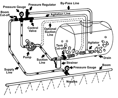 Figure 4. Components of a properly designed weed control sprayer.
Agitators provide the turbulence needed to keep herbicides properly mixed. Herbicides are formulated as liquid concentrates, emulsions, soluble powders, wettable powders and dry flowables. These materials are mixed with water before they are applied. Liquid concentrates, emulsions and soluble powders require little agitation to maintain a good sprayable solution. The bypass hose usually does not furnish enough agitation. Wettable powders require vigorous agitation because they readily settle out. Use jet agitators, sometimes referred to as hydraulic boosters, to maintain proper agitation.
Pumps of four designs (roller, centrifugal, piston and diaphragm) are common on herbicide prayers. Consider three factors in selecting the pump for herbicide sprayers: capacity, pressure and resistance to corrosion and wear. Each pump design offers advantages and disadvantages.
Pump capacity should be sufficient to readily supply the boom output, provide agitation and offset pump wear. If hydraulic, or jet, agitation is used, allow at least 5-7 gpm equivalent mixing action for each 100 gallons of tank capacity. Suitable agitation can also be obtained by pumping 2 gpm per 100 gallons of tank capacity through a siphon, or venturi, agitator that increases the flow through the agitator 2.5 times. Of course, mechanical agitation does not require any pump capacity. Finally, add 20 to 25 percent to spraying and agitation requirements to compensate for loss of power from pump wear.
The pressure control system of a sprayer includes a pressure regulator, pressure gauge and cutoff valve. These components should be within reach of the driver. The pressure regulator regulates the pressure to the nozzles and relieves excess pressures so some of the liquid can return to the tank through the bypass hose. For low-pressure sprayers, a pressure gauge with a 0 to 100 psi range is desirable. A quick-acting cutoff valve handy to the driver is also needed on a sprayer. Often, valves are provided so that each side and the center sections of the boom can be cut off independently.
Boom sprayers get their name from the booms or long spray-bearing arms that extend laterally to cover a particular swath as the sprayer passes over the field. Booms may be “wet” or “dry.” Wet booms use the material of the boom as the conduit for the spray liquid. Pipes or rigid tubes through which the material can pass are used. Dry booms have a rigid boom constructed of angle iron, channel iron or pipes to which hoses and fittings carrying the spray liquid are attached. The spray material passes through the hoses and not the boom itself. Dry boom sprayers are more common. Flexible nozzle spacing, ease of repairs, and cost favor dry booms.
Nozzles meter flow, atomize the liquid in a targeted range of droplet sizes, and disperse the droplets in a specific pattern for proper impact with plants or soil. Nozzles are available in brass, stainless steel, polymer, ceramic and hardened stainless steel. Brass and polymer nozzles are popular, primarily due to low cost. Stainless steel and hardened stainless steel nozzles last three to 15 times longer than brass, but they cost about three to five times more than brass. Ceramic nozzles last about 100 times longer than brass.
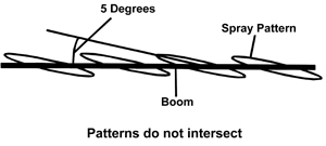 Figure 5. Flat-fan nozzles angled to 5 degrees from the boom.
The type of nozzle used for applying herbicides is one that develops a large droplet and has no drift. The nozzles used for broadcast applications include the regular flat fan, extended range flat fan, drift reduction flat fan, turbo flat fan, twin flat fan, and air induction nozzles. Operating pressures should be 20 to 30 psi. Pressure more than 40 psi can create significant drift. Air induction nozzles and drift reduction nozzles should be operated at 30 psi and above. These nozzles will achieve uniform application of the chemical if they are uniformly spaced along the boom. Flat fan nozzles should be overlap 50 to 60 percent. Table 3 suggest boom heights for flat fan nozzles with different angles. Also, the orientation of each flat fan along the boom should place with an angle of 5 degrees from the center line of the boom (Figure 5).
| Table 3. Suggested Minimum Spray Nozzle Height (Flat Fan). | ||
| Spray Tip Angle | Nozzle Height (Inches)1 | |
| 20" Spacing | 30" Spacing | |
| 80 | 17-19 | 26-28 |
| 110 | 10-12 | 14-18 |
| 1 Nozzle height should be adjusted such that spray pattern overlaps 50-60 percent. | ||
Calibration of Boom Sprayers
Calibration of sprayer equipment is very important. Calibrate sprayers often to guard against using excessive amounts due to nozzle wear, speed changes, and etc. Inaccurate calibration can cost money and may cause crop damage. Safety and economics dictate calibrating with water alone. Be careful while working with sprayers and pesticides in the field. Always carry a plastic jug of clean water on the tractor in case of pesticide contamination.
Orchard herbicide applications are broadcast. Broadcast applications spray 100 percent of area under the boom. In orchards, herbicide strip applications normally spray the orchard floor beneath the trees’ drip line. To determine the sprayed acreage (herbicide strips), divide the herbicide strip width by the tree row width, then multiply by the total acres of trees. This will yield the number of acres to purchase chemical for.
Calibration
The procedure below is based on spraying 1/128 of an acre per nozzle or row spacing and collecting the spray that would be released during the time it takes to spray the area. Because there are 128 ounces of liquid in 1 gallon, this convenient relationship results in ounces of liquid collected being directly equal to the application rate in gallons per acre.
Calibrate with clean water when applying toxic pesticides mixed with large volumes of water. Check uniformity of nozzle output across the boom. Collect from each for a known time period. Each nozzle should be within 10 percent of the average output. Replace with new nozzles if necessary. When applying materials that are appreciably different from water in weight or flow characteristics, such as fertilizer solutions, calibrate with the material to be applied. Exercise extreme care and use protective equipment when active ingredient is involved.
Step 1. From Table 4, determine the distance to drive in the field (two or more runs suggested). For broadcast spraying, measure the distance between nozzles.
Step 2. Measure the time (seconds) to drive the required distance, with all equipment attached and operating. Make note of throttle setting and gear!
Step 3. With sprayer sitting still and operating at same throttle setting or engine RPM as used in Step 2, adjust pressure to the desired setting. Machine must be operated at same pressure used for calibration.
Step 4. Collect spray from one nozzle for the number of seconds required to travel the calibration distance.
Step 5. Measure the amount of liquid collected in fluid ounces. The number of ounces collected is the gallons per acre rate on the coverage basis indicated. For example, if you collect 18 ounces, the sprayer will apply 18 gallons per acre. Adjust applicator speed, pressure, nozzle size, etc., to obtain recommended rate. If speed is adjusted, start at Step 2 and recalibrate. If pressure or nozzles are changed, start at Step 3 and re-calibrate.
Step 6. To determine amount of pesticide to put into a sprayer tank, divide the total number of gallons of mixture to be made (tank capacity for a full tank) by the spray output in gallons per acre(Step 5) and use recommended amount of pesticide for this number of acres.
Step 7. Sprayers should be frequently checked for proper calibration.
Sprayer calibration sheets and wallet size cards are available from your local county extension office.
| Table 4. Calibration distances with corresponding widths. | |
| Nozzle Spacing (inches) |
Calibration Distance (feet) |
| 48 | 85 |
| 36 | 113 |
| 30 | 136 |
| 24 | 170 |
| 20 | 204 |
| 18 | 227 |
| 16 | 255 |
| 14 | 292 |
| 12 | 340 |
| 10 | 408 |
| To determine distance for spacing or band width not listed, divide the spacing or band width expressed in feet into 340.3. Example: For a 13" band, the calibration distance would be 340 divided by 13/12 = 314.1. | |
Status and Revision History
Published on Mar 30, 2006
Published on Feb 23, 2009
Published on May 14, 2009
Published with Full Review on Feb 09, 2012
