Irrigation requires a relatively high investment in equipment, fuel, maintenance and labor, but offers a significant potential for increasing net farm income. Frequency and timing of water application have a major impact on yields and operating costs.
To schedule irrigation for most efficient use of water and to optimize production, it is desirable to frequently determine the soil water conditions throughout the root zone of the crop being grown. A number of methods for doing this have been developed and used with varying degrees of success. In comparison to investment in irrigation equipment, these scheduling methods are relatively inexpensive. When properly used and coupled with grower experience, a scheduling method can improve the irrigator’s chances of success. The following discussion covers the working principles of currently used methods for scheduling irrigation.
Water Balance Method
The principle of the water balance method is shown in Figure 1. The object is to obtain a balance of incoming and outgoing soil water so that adequate available water is maintained for the plant. Inputs include incoming water in any form whether rainfall or irrigation. Outputs include any type of water removal. Water removal is more commonly referred to as evapotranspiration (ET). Evapotranspiration is usually expressed in inches per day. It consists of water removal by the plant (transpiration) and water loss due to evaporation. Two variations of the water balance method are used. One uses crop use curves, the other uses pan evaporation data.
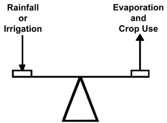 Figure 1. Water Balance Method
To use either variation you must know your soil type and the available water holding capacity of the soil. This may be obtained for your soil from the soil conservation guide from your local Soil Conservation Service. Next, you determine the zone you are trying to manage. This zone will vary according to the effective rooting depth of the particular crop. Usually 24 inches (2 feet) is the most that can be managed with irrigation in southeastern soils. The effective rooting depth of some crops maybe somewhat less. Determine the total water you have available to manage in this zone. It is desirable to try to manage only a percentage of this total water, usually 50 percent. As water is removed daily (ET), these amounts are subtracted from the adjusted water available column.
When the water available approaches a zero balance, it is time to irrigate. The amount to add depends on the soil type but will usually be the same as the 50 percent value calculated earlier plus an added amount to account for application efficiencies less than 100 percent. (Typical application efficiencies for sprinkler irrigation equipment vary from 75 percent to 90 per-cent.) Water-use curves for various crops in Georgia are included at the end of this publication along with pan evaporation coefficients (depending on which method you are using).
Example of Water Balance Method Using Crop Use Curve
Example: Tifton Soil Series. Assuming the upper 24 inches is the rooting depth (hardpans may change this), the total available water is 2.2 inches (from Georgia Irrigation Guide). Assume a 65-day-old corn crop.
Step 1. From the crop curve (see Figure 5), this corresponds to a daily use rate of .32 inches per day.
Step 2. Determine irrigation by setting lower limit for water balance. For this example, use 50 percent as the limit. Then 1.1 inches of water will need to be replaced.
Step 3. Determine amount of irrigation to apply by dividing amount replaced by irrigation efficiency. Using 75 percent as the irrigation efficiency, the amount of irrigation to apply is: 1.1 ÷ .75 = 1.47 inches or 1.5 inches.
Step 4. Determine frequency of irrigation by dividing amount replaced by water use per day. For this example: frequency = 1.1 ÷ .32 = 3.44 = 3.5 days.
Step 5. Therefore it is necessary to apply 1.5 inches every 3.5 days to maintain 50 percent available water on Corn that is 65 days old.
Note: this same procedure can be used for other crops as long as you have the crop water use curve. (See Figures 3 through 11 for additional curves.)
Example of Water Balance Method Using Pan Evaporation Data
Example: Tifton Soil Series. Assuming the upper 24 inches is the rooting depth (hardpans may change this), the total available water is 2.2 inches (from Georgia Irrigation Guide). Assume a 65-day-old corn crop.
Step 1. Local pan evaporation data (available from local weather station) reports daily pan evaporation rates of 0.26 inches per day.
Step 2. The crop coefficient for 65 day old corn (see Figure 13) is 1.06.
Step 3. Determine daily water removal by multiplying daily evaporation by crop coefficient.
0.26 x 1.06 = 0.28 inches
Step 4. Determine irrigation by setting lower limit. For this example use 50 percent. Then 2.2 inches x 50 percent or 1.1 inches will need to be replaced.
Step 5. Determine amount of irrigation to apply by dividing amount replaced by irrigation efficiency. Using 75 percent as the irrigation efficiency, the amount of irrigation to apply is: 1.1 ÷ .75 = 1.47 inches or 1.5 inches.
Step 6. Determine frequency of irrigation by dividing amount replaced by water use per day. For this example 1.1 inches divided by 0.28 inches = 3.93 or 4 days.
Step 7. For this example it is necessary to apply 1.5 inches every 4 days to maintain a balance with pan evaporation.
Note: This same procedure can be used for other crops as long as you have the crop coefficient curve. Figures 12-18 have additional crop coefficient curves.
Soil Moisture Measuring
Several devices are available for monitoring or measuring soil moisture. The most common in use in the field are tensiometers, moisture blocks and various electronic soil probes. Obviously the expense of the device will be a factor. Therefore, it is important to make sure ALL the necessary inputs are considered. A fairly detailed discussion of tensiometers and moisture blocks follows, but most of the discussion is also applicable to probes.
Tensiometers
A tensiometer is a sealed, water-filled tube with a porous ceramic tip on the lower end and a vacuum gauge on the upper end. The tube is installed in the soil with the ceramic tip placed at the desired root zone depth and with the gauge above ground. In dry soil, water is drawn out of the instrument, reducing the water volume in the tube and creating a partial vacuum which is registered on the gauge. The drier the soil, the higher the reading. When the soil receives water through rainfall or irrigation the action is reversed. The vacuum inside the tube draws water from the soil back into the instrument which in turn results in lower gauge readings.
The amount of vacuum reflected by the gauge is a direct measure of soil water tension or soil suction. The standard unit of measurement of soil water tension, or soil suction, is the “bar.” The bar is a unit of pressure (or vacuum) in the metric system and is approximately equivalent to one atmosphere or 14.5 lbs./sq. in. Most tensiometer gauges are calibrated in hundredths of a bar (called centibars) and graduated from zero to 100. In these units of calibration a tensiometer can operate in a range of 0 to 80 centibars.
Plant roots must overcome the soil suction or the attraction that soil particles have for water in the soil in order to withdraw and use this water. The measurement of soil suction is a direct indication of the amount of work the plant roots must do to get water from the soil. The tensiometer measures soil suction directly without calibration for soil type, salinity or temperature. Generally, you can select a location where measurement devices will not be in the way of field operations. Mark stations so you can avoid them with only minor inconvenience to equipment operators. To protect against accidental striking by tools or machinery, drive stakes near the instruments with colored flags or tape attached. You can also cover them with a box, a tile, a steel pipe or similar protective device (provided water movement within the soil is not impeded).
Installation
Install tensiometers so the tip is in the active root zone of the crop grown. Usually one depth will be needed for plants having active root zones less than 15 inches, but use two for plants having active roots deeper than 15 inches. For deeper rooted plants or in orchards it may be desirable to have instruments at three different depths. (See Figure 2.)
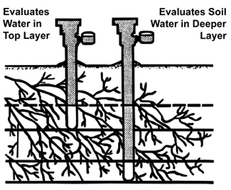 Figure 2. Typical Tensiometer Location
For most crops and soils, two depths per station are recommended. Set one with the tip at a depth between one-fourth and one-half of the root zone and the other at a depth of about three-fourths of the active root zone. Use the shallow tensiometer for scheduling the “start” of the irrigation cycle. Use the deep tensiometer to evaluate if the proper “amount or depth” of water was applied. When soil water is known at these depths, an accurate estimate can be made of water conditions throughout the root zone.
One method recommends inserting the ceramic tip into a prepared hole so that the walls of the tip are in close contact with undisturbed soil and roots. Prepare the hole by driving a steel rod or pipe of the same diameter as the instrument tube to the desired depth. Carefully remove the rod and push the tensiometer to the bottom of the hole. Press soil around the tensiometer at the surface and pile it slightly so water will not collect and seep down along the tube of the tensiometer.
Another method often used for installing tensiometers with equally good results is to bore the hole with a soil auger (1¼ inches) to the desired depth. Next make a slurry in the bottom of the hole with screened soil, place the tensiometer and backfill with screened soil, tamping the soil firmly around the tube with a ½-inch dowel.
Servicing
When preparing a tensiometer for installation, follow the manufacturer’s recommendations. This includes filling the instrument with solution and removing air from the gauge, the pores of the ceramic tip and all internal plastic parts. A service unit is available from some manufacturers which includes a hand vacuum pump for removing air and testing the gauge.
The tensiometer may need occasional refilling with water. The best time to add water is after an irrigation when the vacuum is low. After refilling, the vacuum pump may be used to remove air bubbles.
Interpreting Tensiometer Gauge Readings
Tensiometer readings reflect the relative wetness of the soil (high readings indicate a dry soil, low readings a wet soil). Although you can assume some general interpretations of the readings, experience irrigating specific soil and crop will enable more accurate evaluations of soil-water conditions.
The following general guidelines to interpreting gauge readings may be used under most conditions:
Readings 0-5 — This range indicates a nearly saturated soil and often occurs for one or two days following a rain or irrigation. Plant roots may suffer from lack of oxygen if readings in this range persist.
Readings 5-20 — This range indicates field capacity. Discontinue irrigation in this range to prevent waste of water by percolation and also to prevent leaching of nutrients below the root zone.
Readings 20-60 — This is the usual range for starting irrigation. Most field plants having root systems 18 inches deep or more will not suffer until readings reach the 40 to 50 range. Starting irrigations in this range insure maintaining readily available soil water at all times. It also provides a safety factor to compensate for practical problems such as delayed irrigation, or inability to obtain uniform distribution of water to all portions of the field.
Readings 70 and Higher — This is the stress range for most soils and crops. Deeper rooted crops in medium textured soils may not show signs of stress before readings reach 70. A reading of 70 does not necessarily indicate that all available water is used up, but that readily available water is below that required for maximum growth. For readings above 70, tensiometers are likely to break tension (The vacuum is destroyed.) especially in coarser textured soils.
For irrigation systems that require several days to cover a given field (such as a center pivot), it will be necessary to anticipate how high the tension will go before the system reaches a given location in the field. In these cases it will be necessary to start the irrigation system at lower tensiometer readings so that some sections of the field do not get too dry before the system gets there. For instance, it is not unusual to start a center pivot at tensiometer readings of 15 or 20. This is especially true in the sandier soils which have a relatively low water holding capacity.
Electrical Resistance Meters
How They Work
Electrical resistance meters determine soil water by measuring the electrical resistance between two wire grids embedded in a block of gypsum or similar material that is permanently embedded in the soil. The electrical resistance of the block varies with its water content, which in turn is dependent upon the water content of the soil in contact with it. As the soil dries, the block loses water and the electrical resistance increases. Therefore, resistance changes within the block as measured by the meter can be interpreted in terms of soil water content.
The blocks, which have stainless steel electrodes embedded in them, are installed permanently at desired locations and depths in the soil. Insulated wires from each block are brought above the soil surface where they can be plugged into a portable meter for reading.
Calibration
Resistance blocks are generally calibrated in terms of soil water tension so as to make readings applicable across soil textures. Blocks should be calibrated for each soil type. The way blocks manufactured by different companies respond to changes in soil water tension varies considerably. For this reason each manufacturer furnishes calibration curves for their own instruments and blocks.
Installation of the Blocks
- Soak blocks in water according to manufacturer’s recommendations before installation. Soaking removes air from the blocks and insures accurate meter readings.
- Using a soil probe or auger, bore a hole in the row slightly larger than the gypsum block. Make a separate hole for each block to desired depth.
- Crumble up at least 3 inches of soil removed from the hole and put it back into the hole. Pour about ½ cup of water into the hole to form a slurry of mud in the bottom.
- Push the block firmly to the bottom of the hole, forcing the slurry to envelop the block. A good way to do this is to use a section of ½-inch electrical conduit or pipe; slip the conduit over the lead wire and against the top of the block.
- Back fill the holes with soil 3 or 4 inches at a time, tamping firmly as the hole is filled.
- Drive a stake midway between the filled holes and tie the wire leads to the stake. Be sure to mark the wires in some manner so that you can identify which one is for the shallow block and which one is for the deeper block.
Depth of Installation
The active root zone of the crop determines the depth at which to place the blocks. Type of crop, soil depth and stage of growth largely determine the active root zone.
Install the blocks soon after planting to allow time for plant roots to grow around the blocks and to assure a positive contact between blocks and soil. Any separation between blocks and surrounding soil will lead to inaccurate readings.
When the seeds are first planted, irrigation may be needed to assure quick and uniform seed germination. Visual inspection of the soil near the seeds will indicate whether irrigation is needed. A minimum of two blocks per station is recommended; one shallow, one deep. Use the shallow block for scheduling the “start” of the irrigation cycle. Use the deep block to evaluate if the proper “amount or depth” of water was applied. Table l gives recommended depths for setting the blocks according to soil depth or active root zone.
| Table 1. Recommended Depths for Placing Electrical Resistance Blocks According to Soil Depth or Active Root Zone | ||
| Soil Depth or Active Root Zone (inches) | Shallow Blocks (inches) | Deep Blocks (inches) |
| 18 | 8 | 12 |
| 24 | 12 | 18 |
| 36 | 12 | 24 |
Soil depth may be the limiting factor in determining the active root zone. Soils that have loamy sand or finer textured soil overlying an impermeable layer limit the potential root zone of deeper rooting crops. When soil depth is limiting, consider soil depth rather than active root zone when determining how deep to place the blocks.
The following generalizations apply to installation of all blocks:
- The soil water measured is only that immediately surrounding the blocks. It is important that the location is representative of the area concerned.
- Place blocks in undisturbed soil if at all possible. When this is not possible, place at least one side of the blocks against undisturbed soil.
- Duplicate installations 10 to 15 feet apart are desirable for checking readings.
- Soak blocks, then install them in moist soil.
Interpreting Electrical Resistance Meter Readings
Available soil water may be expressed either in percent of the total potential reserve or in terms of suction necessary to draw water from the soil particles. Such suction is referred to as negative pressure or tension, measured in bars.
Table 2 is a guide to interpreting meter readings as they relate to soil water tension for one type meter. Graduations on the meter scale will not be the same for all makes or models and will vary with soil type. Meter manufacturers, however, always provide instructions for interpreting readings.
| Table 2. Interpretation of Readings on Electrical Resistance Meters as Related to Soil Water Tension | |||
| Bars Tension | Meter Readings* | Interpretation | |
| Nearly saturated | less than 0.05 | 0 to 5 | Near saturated soil. Occurs for a few hours following a rain or irrigation. |
| Field capacity | 0.10 to 0.20 | 5 to 20 | Field capacity. Irrigations discontinued in this range. |
| Irrigation range | 0.20 to 0.60 | 20 to 60 | Usual range for starting irrigation. Starting irrigation in this range insures maintaining readily available soil moisture at all times. |
| Dry | greater than 0.60 | more than 60 | Stress range for most soils and crops. Some soil moisture present but dangerously low for maximum plant growth and production. |
| * These readings will vary according to meter type and soil type. | |||
When to Start Irrigation
Instrument readings that indicate the need for irrigation will be different for various textured soils, (see table 3). Start irrigation sooner on a sandy soil than on a clay soil, because sandy soils hold less water than clay soils at the same meter reading. When scheduling take into account the time required for the system to complete irrigation of the entire field. Otherwise, the last part of the field to receive water may become too dry.
Start irrigation at lower meter readings during hot weather, high winds or low humidity, since loss of water is accelerated by these conditions.
| Table 3. Electrical Resistance Meter Readings for Starting Irrigation | ||
| Meter Readings on Shallow Block* | ||
| Soil | Meter Reading | Bar Tension |
| Loamy sands; Sandy loams; Very fine sandy loams | 25 | 0.25 |
| Silt loams | 40 | 0.40 |
| Clay loams & Silty clay loams | 60 | 0.60 |
| * These are average readings and will vary depending on crop, rooting depth, type of irrigation system, meter and soil type. | ||
Location of Stations (all devices)
There should be at least one, and preferably two, measurement locations (two or more devices at one location being a station) for each area of the field that differs in the soil type and depth. A station located in each different soil type enables you, through timing and duration of irrigation to maintain the same amount of available water in all areas.
Try to select representative areas of the field for a station. However do not place them in low spots as they are not representative. It may be best to limit the total number of stations until you gain experience. After a trial period it will be easier to determine the total number needed.
Always try to place devices in accessible locations so that the operator can get to them relatively easily.
Computer Models
Computer models are being developed and updated each year. To use a computer model you obviously must have access to a computer on a regular basis. Simple models are available that do “checkbook” type record keeping. More sophisticated models are available that require weather data inputs (you can supply these inputs manually or some programs will record the data directly from an in-field weather station.) Models can also incorporate other management decisions such as whether to spray for insects and diseases. Models of the later type are called expert systems. Computer models can be very beneficial in decision making. However, the statement “Garbage in – Garbage out” is very applicable for computer models. Be certain that the model is applicable to your geographical area and that the input data you supply is valid or the results could be misleading.
Keeping a Chart
You can obtain the full benefit of using tensiometers, electrical meters or computer models by recording soil moisture readings and plotting them on a chart. Readings may be plotted directly in the field. Use different colored pencils for different depth tensiometers (or soil blocks) to make the chart easier to read. The chart lines show what has happened in the past. By projecting them ahead, you have an advance indication of what you can expect in a few days. This information is helpful in scheduling the next irrigation and in measuring the effectiveness of an irrigation — what depth of penetration was achieved and how soon the soil dried out. Most manufacturers include charts with their instruments. If not included, they can easily be made. Record rainfall data along with the instrument reading to aid in evaluating soil water conditions.
| Table 4. Comparison of Methods | ||||
| Balance Method | Tensiometers | Resistance Blocks | Computer Models | |
| Expense | No expense | Moderate expense | Moderate expense | Expensive* |
| Accuracy | Fair | Good | Good | Fair** |
| Operate Automated Equipment | No | Yes | Yes | Yes |
| Repeatability | Fair | Good | Fair | Good |
| * Varies depending on if computer already exists in farming operation. ** Computer models are only as accurate as the data used for inputs (i.e., weather, rainfall, etc.). |
||||
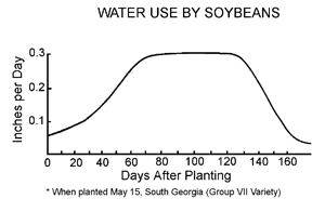 Figure 3.
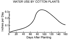 Figure 4.
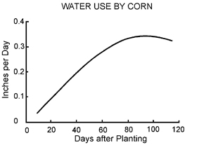 Figure 5.
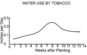 Figure 6.
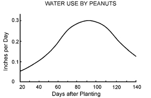 Figure 7.
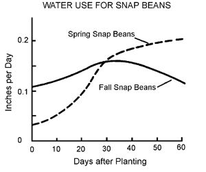 Figure 8.
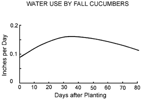 Figure 9.
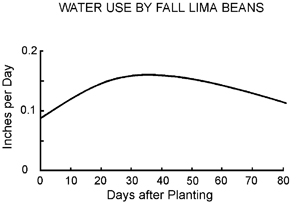 Figure 10.
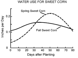 Figure 11.
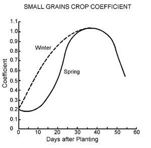 Figure 12.
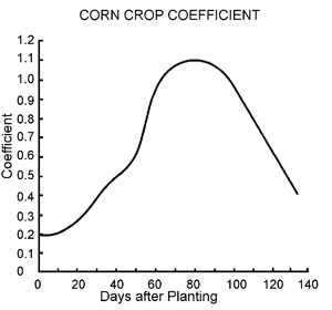 Figure 13.
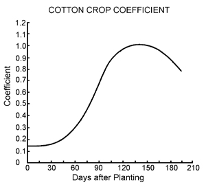 Figure 14.
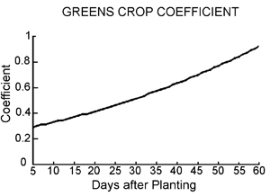 Figure 15.
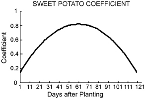 Figure 16.
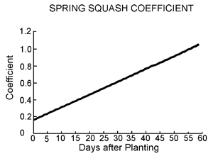 Figure 17.
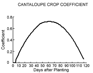 Figure 18.
Status and Revision History
Published on Nov 15, 2005
Published on Feb 23, 2009
Published on May 14, 2009
Published with Full Review on Apr 25, 2012


